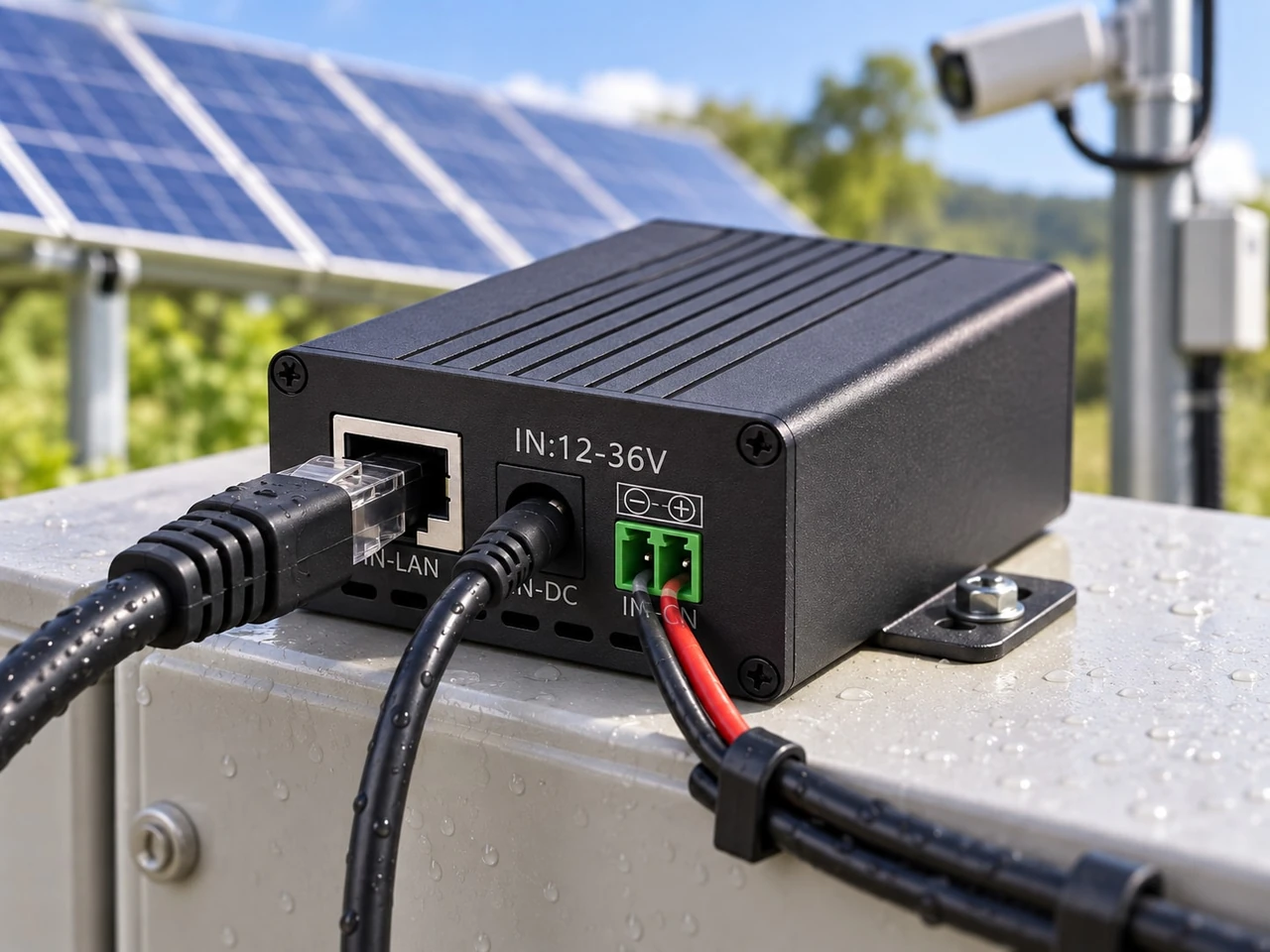
How to Size Solar Power for an Outdoor PoE Device
Learn how to size battery storage and solar input for outdoor PoE devices using measured loads, explicit losses, autonomy and design-month sun.
By Maxsol Team

To calculate solar power requirements for an outdoor PoE device, first measure the complete load at the solar system’s DC output—not just the wattage printed on the powered device. Convert each operating mode into watt-hours per day, add auxiliary consumption, choose the required days of autonomy and usable battery fraction, then size the solar array using the site’s design-month peak sun hours and a documented system-loss factor.
Keep energy sizing separate from PoE compatibility. A battery and panel may have enough watt-hours, yet still be unsuitable if the converter has the wrong output voltage, polarity, pinout, protocol or continuous power rating.
A practical calculation follows these relationships:
- Daily energy: operating watts × operating hours
- Required nominal battery energy: daily watt-hours × autonomy days ÷ usable battery fraction
- Required solar array: daily watt-hours ÷ design-month peak sun hours ÷ solar delivery factor
Every input should come from a measurement, equipment document or project-approved design assumption.
Define the complete PoE load and duty cycle
Begin by identifying everything that will draw power from the off-grid system. For a simple installation, this may be one PoE camera and one DC-to-PoE converter. A larger site may also include a wireless bridge, router, industrial switch, illuminator, controller, heater, fan or monitoring module.
Do not size the system from the PoE device’s headline rating alone. The complete load can include:
- The powered device, such as a camera, access point or CPE bridge
- A PoE injector, converter or switch
- An upstream radio, router or fibre media converter
- Cabinet ventilation, heating or environmental controls
- Relays, sensors and remote monitoring devices
- Standby consumption from equipment that remains energised
- Night-time functions such as infrared illumination
- Start-up or transient demand that may exceed normal running power
For multiple PoE devices, calculate each load separately before adding the results. This makes it easier to identify equipment with different schedules or night-time power behaviour.
| Load | Operating mode | Measured power | Hours per day | Daily energy |
|---|---|---|---|---|
| PoE device 1 | Day mode | (P_1) W | (H_1) h | (P_1 \times H_1) Wh |
| PoE device 1 | Night mode | (P_2) W | (H_2) h | (P_2 \times H_2) Wh |
| Wireless link | Continuous | (P_3) W | 24 h | (P_3 \times 24) Wh |
| Auxiliary load | Scheduled | (P_4) W | (H_4) h | (P_4 \times H_4) Wh |
If a camera uses more power when infrared LEDs, a heater or pan-tilt-zoom movement is active, measure those conditions rather than relying only on an idle reading. For surveillance projects, the process in this guide can be used together with a more detailed PoE power budget calculation for security cameras.
Use source-side measurement where possible
The most useful measurement point is the DC input feeding the converter or PoE equipment. A source-side reading captures the actual combined effect of the powered device, conversion loss and immediate wiring.
Record at least:
- Normal daytime power
- Maximum sustained night-time power
- Start-up behaviour
- Any scheduled auxiliary loads
- The input voltage during each test
- Current and power at both the source and device ends, where practical
A brief bench reading may miss cycling loads or changing radio transmit activity. Logging power over a representative operating period gives a better basis for design.
Add converter, cable and auxiliary losses
If only powered-device wattage is known, conversion and cable losses must be added explicitly. Do not assume that a 15W device requires exactly 15W from the battery.
For a converter with an approved design efficiency of (η):
[ P_{\text{converter input}} = \frac{P_{\text{device}}}{η} ]
Then include measurable cable and auxiliary loads:
[ P_{\text{total}} = P_{\text{converter input}} + P_{\text{cable loss}} + P_{\text{auxiliary}} ]
Efficiency must be written as a decimal in the formula. For example, a project-approved 90% assumption would be entered as 0.90. This number is only an illustration of how the formula works; it is not a universal converter efficiency or a recommended design value.
Account for both DC and Ethernet cable losses
There may be two relevant cable sections:
- The low-voltage DC cable between the battery or controller and converter
- The Ethernet cable carrying PoE from the converter to the outdoor device
DC cable loss can be determined from voltage drop and current:
[ P_{\text{DC cable loss}} = V_{\text{drop}} \times I ]
PoE cable loss depends on conductor resistance, current, cable length, conductor size, temperature and the pairs used for power. Long runs at higher current deserve particular attention. Measure voltage at the powered device under its highest sustained load rather than checking only the no-load output.
Increasing the PoE voltage can reduce current for the same delivered power, but voltage must never be changed without confirming the powered device’s permitted input, protocol and pinout.
Avoid counting losses twice
There are two valid approaches:
- Measured source-side method: use the watts measured at the solar controller or battery output. Converter and immediate cable losses are already included.
- Component method: start with device watts and add conversion, cable and auxiliary losses separately.
Do not measure source-side power and then add the same converter loss again.
The POE24V DC-to-PoE power converter accepts 12–36V DC and provides adjustable 12–57V PoE output, Gigabit Ethernet and an LCD voltage display. Its documented continuous load when converting 12V to 48V is no more than 30W. The stated conversion efficiency of up to 94% is a maximum, not a guaranteed design efficiency. Use measured input power or an appropriately conservative, project-approved assumption.
Convert power into daily energy demand
Solar systems are sized in energy, not watts alone. Watts describe the instantaneous load, while watt-hours describe the energy consumed over time.
For every operating mode:
[ E = P \times H ]
Where:
- (E) is energy in watt-hours
- (P) is power in watts
- (H) is operating time in hours
Add all operating modes to obtain daily demand:
[ E_{\text{daily}} = E_1 + E_2 + E_3 + \ldots ]
Illustrative calculation
Consider a design worksheet with the following measured source-side values:
- Combined daytime load: 18W for 12 hours
- Combined night-time load: 26W for 12 hours
- Separate auxiliary load: 3W for 24 hours
The daily calculation is:
[ (18 \times 12) + (26 \times 12) + (3 \times 24) ]
[ 216 + 312 + 72 = 600Wh/day ]
These figures are illustrative calculation inputs, not expected consumption for a particular camera, radio or Maxsol product.
For intermittent equipment, use its realistic duty cycle. A 20W load operating for 15 minutes each hour does not consume 480Wh per day:
[ 20W \times 0.25h \times 24 = 120Wh/day ]
However, a duty-cycle estimate is only suitable when operating behaviour is predictable. Critical security and communications equipment should be checked for prolonged high-load conditions, such as continuous recording activity, night illumination or heavy wireless traffic.
Select autonomy and usable storage assumptions
Autonomy is the number of days the system should support the load when solar charging is insufficient. It is a project requirement, not a universal value.
The required nominal battery energy is:
[ E_{\text{battery nominal}} = \frac{E_{\text{daily}} \times D_{\text{autonomy}}} {F_{\text{usable}}} ]
Where:
- (E_{\text{daily}}) is the daily load in Wh
- (D_{\text{autonomy}}) is the selected number of days
- (F_{\text{usable}}) is the approved usable fraction of nominal battery energy
The usable fraction must reflect the battery design, battery management limits, discharge-rate effects, temperature, ageing allowance and the project’s required reserve. Do not treat the nominal watt-hour label as fully deliverable energy.
For example, if a project team has approved two autonomy days and a usable fraction of 0.80 for its specific design, the illustrative 600Wh/day load would require:
[ \frac{600 \times 2}{0.80} = 1,500Wh ]
The 0.80 figure is an example input only. It is not a declared usable percentage for the products discussed here.
Compare batteries using nominal energy first
Amp-hours alone are not enough unless battery voltage is also considered:
[ Wh = V \times Ah ]
Two relevant calculation references are:
- The CS8040 80W solar system with 45Ah 576Wh battery, which documents an 80W monocrystalline panel, 12.8V 45Ah 576Wh LiFePO4 battery, MPPT controller and three DC12V outputs.
- The CS12060 120W solar system with 60Ah 768Wh battery, which documents a 120W monocrystalline panel, 12.8V 60Ah 768Wh LiFePO4 battery, MPPT controller and three DC12V outputs.
The 576Wh and 768Wh figures are nominal storage capacities. They must not be interpreted as guaranteed usable energy or runtime. Apply the project’s approved usable-energy assumption and verify that the output arrangement suits all connected equipment.
For a broader system-level worksheet covering cameras and off-grid storage, see the guide to sizing an off-grid solar power system for CCTV.
Estimate design-month solar input
The panel must replace the energy used each day while also supporting system losses. Size it using solar input for the most demanding design month, not an annual average that may hide periods of lower generation.
The basic relationship is:
[ P_{\text{array}} = \frac{E_{\text{daily}}} {H_{\text{design}} \times F_{\text{solar delivery}}} ]
Where:
- (P_{\text{array}}) is the required rated array power in watts
- (E_{\text{daily}}) is daily demand in Wh
- (H_{\text{design}}) is design-month peak sun hours
- (F_{\text{solar delivery}}) represents approved derating and charging assumptions
Obtain design-month solar data for the actual Malaysian project location and intended panel orientation. Do not substitute a generic nationwide peak-sun-hours figure. Local shading, terrain, nearby structures, vegetation, cloud patterns and installation angle can materially affect usable input.
The solar delivery factor may need to address:
- Panel temperature
- Soiling and water marks
- Wiring loss
- Controller conversion
- Battery charging loss
- Panel mismatch
- Orientation and tilt
- Partial shading
- Equipment ageing or project reserve, where specified
Each allowance should be stated rather than hidden inside an unexplained margin.
Compare panel options against required daily harvest
A convenient comparison formula is:
[ E_{\text{estimated harvest}} = P_{\text{panel}} \times H_{\text{design}} \times F_{\text{solar delivery}} ]
Therefore:
- An 80W panel has estimated design-day input of (80 \times H_{\text{design}} \times F_{\text{solar delivery}})
- A 120W panel has estimated design-day input of (120 \times H_{\text{design}} \times F_{\text{solar delivery}})
Compare the resulting watt-hours with the complete daily load. The result should satisfy the project’s charging and recovery requirements, not merely equal an idealised average-day load.
Also check whether the array can restore battery energy after an autonomy event. A design that just balances consumption on an average day may take too long to recover after several low-generation days.
Verify voltage, protocol and commissioning measurements
Energy capacity does not establish PoE compatibility. Before connecting equipment, verify the full electrical and network interface.
PoE checks
Confirm:
- Required powered-device voltage range
- Converter output voltage setting
- Maximum continuous device power
- Start-up and transient power
- Polarity
- Power pinout and pair assignment
- Active or passive PoE operation
- IEEE detection or negotiation requirements
- Ethernet data rate and pair usage
- Maximum cable distance and acceptable voltage drop
The documented facts for POE24V do not establish IEEE powered-device detection or negotiation. Treat it as a converter that requires verification of voltage, polarity, pinout and protocol compatibility. Do not assume that an RJ45 connection alone makes two devices compatible.
The linked solar systems and converter are calculation examples, not a tested compatible bundle.
Commissioning checks
After installation, record actual values under realistic operating conditions:
- Battery or controller output voltage
- Total source-side current and watts
- Converter input and output voltage
- Powered-device voltage at the far end of the cable
- Day and night energy use
- Highest sustained load
- Start-up behaviour after a low-voltage shutdown
- Charging current and daily solar input
- Battery state at the same time on successive days
- Network stability while the device is at maximum load
Repeat checks during the design season where practical. A system commissioned only during favourable solar conditions may not reveal an undersized array, excessive shading or insufficient storage.
Common sizing mistakes to avoid
- Using the device’s maximum watts as daily energy: watts must be multiplied by operating hours.
- Ignoring night mode: cameras and other devices may consume more after dark.
- Omitting converter loss: output power and battery-side input power are not identical.
- Treating nominal battery Wh as usable Wh: discharge limits and system losses reduce delivered energy.
- Using annual-average sun data: design-month input is more relevant for an off-grid critical load.
- Adding a vague safety margin: identify individual loss and reserve assumptions so they can be reviewed.
- Sizing only for normal operation: check start-up, recovery charging and prolonged high-load modes.
- Assuming all PoE is interchangeable: voltage, negotiation, polarity and pinout must be verified.
- Ignoring cable voltage drop: a converter may show the correct voltage while the remote device receives less.
- Combining unknown loads into one estimate: measure each device or branch so future changes can be assessed.
Final sizing checklist
Before selecting equipment, confirm that the design file contains:
- A complete load list
- Measured watts for every important operating mode
- Operating hours or duty cycles
- Explicit converter and cable losses
- Total daily demand in Wh
- Approved autonomy days
- Approved usable battery fraction
- Required nominal storage in Wh
- Site-specific design-month solar input
- Explicit panel and charging derating assumptions
- Required recovery performance
- Verified DC voltage and current limits
- Verified PoE voltage, polarity, pinout and protocol
- Commissioning measurements at source and load
As a practical next step, compare the linked Maxsol system examples and converter against the project’s port count, measured load, cable distance, power requirement, environment and management needs. Complete the energy calculation first, then verify electrical and PoE compatibility separately before specifying a final configuration.