Solar Power and PoE for Off-Grid Networking
Learn how to combine solar power and PoE for off-grid cameras and networks, including power paths, compatibility checks and practical limitations.
By Maxsol Team

Solar power and Power over Ethernet (PoE) can work together to run an IP camera, wireless bridge or access point where grid electricity is unavailable. The solar system charges a battery, while a compatible DC-to-PoE interface converts stored battery power into the voltage and pin arrangement required by the network device.
The key point is that solar power supplies energy, not network data. Ethernet data must still come from a router, switch, recorder, wireless bridge or another network source. Reliable solar power and PoE off-grid networking therefore depends on matching two separate paths: the electrical power path and the communications path.
Trace the solar energy and Ethernet data paths
A typical off-grid PoE installation has two paths that meet at the DC-to-PoE interface.
Energy path:
Solar panel → charge controller → battery → DC-to-PoE interface → powered device
Data path:
Router, switch, NVR or wireless bridge → Ethernet cable → DC-to-PoE interface → powered device
The PoE interface combines DC power with Ethernet data for the final cable run to the camera, access point or customer premises equipment (CPE). Depending on the interface design, it may act as a passive injector or perform standards-based PoE detection and negotiation.
| Stage | Main function | What to verify |
|---|---|---|
| Solar panel | Generates DC electricity from sunlight | Voltage, current and power limits of the controller |
| Charge controller | Regulates battery charging | Battery chemistry, charging profile, protection and temperature limits |
| Battery | Stores energy for night-time and low-generation periods | Nominal voltage, operating range, capacity and protection behaviour |
| DC-to-PoE interface | Converts battery voltage and places power onto Ethernet conductors | Input range, output voltage, power limit, polarity, pinout and protocol |
| Ethernet source | Supplies network data | Port speed, network configuration and connection to the wider system |
| Powered device | Uses both power and data | PoE standard or passive input requirements, peak demand and cable limits |
Adding solar power to an existing PoE camera
If a camera already receives data and power from a conventional PoE switch, moving it off-grid is not simply a matter of replacing the switch with a solar panel.
First, identify:
- The camera’s accepted PoE standard or passive input voltage.
- Its normal consumption and highest startup demand.
- Whether its Ethernet connection comes from a local recorder, router or wireless bridge.
- Whether the proposed DC-to-PoE device supports the required voltage, polarity, pin assignment and power.
- How the battery and controller will maintain a stable DC supply throughout their operating range.
If the camera uses IEEE 802.3af, 802.3at or 802.3bt, do not assume that any adjustable PoE injector can power it safely. The interface must provide the electrical behaviour expected by that camera, including negotiation where required.
Separate charging, storage and PoE functions
An off-grid networking system is easier to specify when each component has one clearly understood role.
Solar charging equipment
The panel and charge controller manage energy generation and battery charging. They do not normally decide whether a connected camera is an IEEE PoE powered device.
For example, the Maxsol CS12060 120W and 768Wh solar system documents:
- A 120W monocrystalline solar panel
- A 12.8V 60Ah, 768Wh LiFePO4 battery
- An MPPT charge controller
- Three DC12V outputs
- Optional RS485
These specifications describe the system’s nominal components, not a guaranteed runtime for a particular camera or networking load. Before selection, verify the current controller limits for PV voltage, current and power, together with battery charging temperatures and the protection settings of the supplied configuration.
Energy storage
The battery supplies the load when solar generation is insufficient, including at night. Its nominal watt-hour rating is not the same as usable energy delivered to the device.
Available energy can be reduced by:
- Battery management system limits
- Low-voltage cut-off settings
- Converter losses
- Cable losses
- Charge-controller and auxiliary consumption
- Temperature conditions
- Battery state of charge
- Age and operating history
For this reason, dividing nominal battery watt-hours by camera wattage does not establish a dependable runtime.
DC-to-PoE conversion
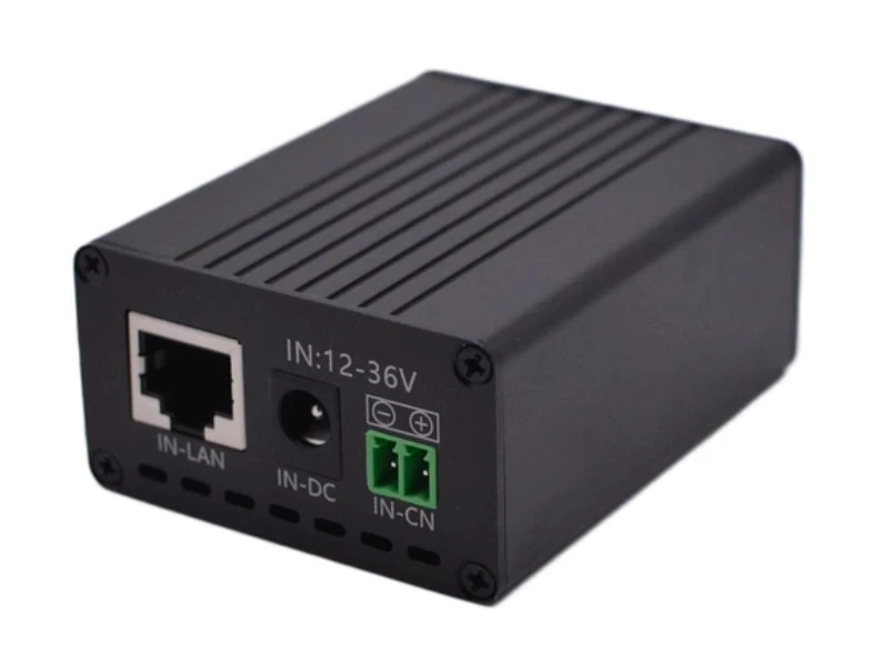
The converter or injector takes battery-side DC and produces the voltage used on the Ethernet cable. It must be evaluated separately from the solar charging system.
The Maxsol POE24V DC-to-PoE power converter documents a 12–36V DC input, adjustable 12–57V PoE output, Gigabit Ethernet and an LCD voltage display. Its documented continuous load when converting 12V to 48V is no more than 30W.
Its maximum stated conversion efficiency is up to 94%, but that is not a guaranteed design efficiency under every input voltage, output setting and load. IEEE powered-device detection or negotiation is also not established by the supplied facts. Voltage, polarity, pinout and protocol compatibility must therefore be confirmed before connecting equipment.
The linked solar system and converter are selection examples, not a tested or confirmed compatible bundle.
Distinguish passive PoE from IEEE negotiation
Passive PoE and IEEE-standard PoE may use similar Ethernet cables, but their behaviour is fundamentally different.
| Attribute | Passive PoE | Negotiated IEEE PoE |
|---|---|---|
| Initial power behaviour | Usually places a fixed voltage on selected conductors | Detects a valid powered device before applying full power |
| Voltage selection | Determined by injector or converter setting | Determined by the relevant IEEE implementation |
| Device identification | Usually none | Uses detection and, depending on implementation, classification or negotiation |
| Main compatibility checks | Voltage, polarity, pinout, current and power | Supported IEEE standard, power class, port capability and cable conditions |
| Risk of a mismatch | Incorrect voltage or pinout may damage equipment | A compliant source should not apply full power to an unrecognised device |
| Typical specification wording | “Passive 24V”, “48V passive” or a stated pin assignment | IEEE 802.3af, 802.3at or 802.3bt |
A variable voltage control only changes the output voltage. It does not, by itself, add IEEE detection, classification or negotiation.
For example, setting an adjustable passive injector to 48V does not automatically make it an IEEE 802.3af or 802.3at power sourcing device. Conversely, a camera described as “PoE” should not be assumed to accept passive power unless its documentation explicitly states the supported voltage and pinout.
Camera and powered-device compatibility checklist
Check the following information on the camera, access point or bridge datasheet:
- Is the input IEEE 802.3af, 802.3at or 802.3bt?
- Does it instead specify passive PoE?
- What is the accepted voltage range?
- Which Ethernet pairs or pin assignments carry power?
- What polarity is required?
- What is the continuous power consumption?
- Is there a higher startup, infrared, heater or radio-transmit demand?
- Does the device use Gigabit Ethernet, and does the interface preserve all required data pairs?
- Is the device designed for the site’s temperature, moisture and enclosure conditions?
When documentation is incomplete, confirm the requirement with the equipment supplier rather than relying on connector appearance or nominal voltage alone.
Match battery and converter operating voltages
Nominal voltage is only a label. A battery identified as 12V or 12.8V operates across a range that changes with charging state, load and protection behaviour.
The converter’s full accepted input range must cover the battery system’s actual output range. It should remain within specification when:
- The battery is being charged
- The battery is near its normal upper operating voltage
- A load causes a temporary voltage drop
- The battery approaches low-voltage cut-off
- Long DC cables create additional voltage loss
The PoE output must then match the powered device. Turning up the output to compensate for cable loss is unsafe unless the resulting voltage at both ends remains inside the device’s documented limits.
Check the complete voltage chain
Use this sequence:
- Confirm the charge controller’s regulated output arrangement.
- Confirm the battery’s normal and protected operating range.
- Confirm the converter’s DC input range.
- Confirm the converter’s available continuous output at the intended input and output voltages.
- Confirm the powered device’s accepted PoE voltage, protocol, polarity and pinout.
- Estimate voltage drop over both the DC cable and Ethernet cable.
- Check how the system behaves at startup and low battery voltage.
A converter accepting 12–36V DC may appear suitable for a nominal 12.8V battery, but input-range overlap alone does not prove complete system compatibility. Connector type, protection settings, output protocol and load demand remain separate checks.
Budget continuous and startup demand
A solar-powered PoE system must support more than the wattage printed beside a camera’s normal operating figure. Design checks should include continuous load, peak demand and conversion overhead.
For multi-device systems, a structured PoE power budget for security cameras helps identify the total demand at the power source. For a single off-grid device, the same principles apply even when no conventional PoE switch is used.
Hypothetical power example
The following figures are assumptions for explanation only. They are not measured product performance or a sizing recommendation.
Assume that a camera requires:
- 12W during normal operation
- 18W briefly during startup or infrared activation
- A design conversion efficiency assumption of 85%
The estimated converter input during normal operation would be:
12W ÷ 0.85 = approximately 14.1W
During the hypothetical peak:
18W ÷ 0.85 = approximately 21.2W
Additional DC cable and connector losses may raise the battery-side demand. This example also does not include a wireless bridge, router, recorder, controller consumption or enclosure equipment.
Although a converter may have a documented 30W continuous limit under a particular 12V-to-48V condition, a calculated load below 30W is not enough to confirm suitability. Startup behaviour, output voltage, protocol, thermal conditions and the actual input voltage must also be checked.
Loads that are easily overlooked
Include all equipment drawing energy from the same battery:
- IP cameras
- Infrared illuminators
- PTZ motors
- Wireless bridges or access points
- Routers and cellular networking equipment
- Ethernet switches
- Charge controller consumption
- DC converters
- Cabinet fans or heaters, where fitted
- Monitoring and control equipment
Some cameras consume more power when infrared LEDs switch on, when a motor moves or when internal heating is active. Wireless devices may also have short transmit peaks. Use the highest documented demand rather than relying only on an average figure.
Daily energy demand and solar replenishment require a separate assessment. The practical process is covered in the guide to sizing an off-grid solar power system for CCTV. No panel-and-battery combination can provide a universal autonomy or 24/7 guarantee without defined loads, operating conditions and design assumptions.
Review a compatible architecture checklist
Before purchasing or installing equipment, review the complete architecture rather than assessing each component in isolation.
1. Solar generation and charging
- Is the panel electrically compatible with the controller?
- Are controller PV voltage, current and power limits confirmed?
- Does the controller use the correct charging profile for the battery?
- Are charging-temperature restrictions understood?
- Are panel orientation, shading and mounting conditions assessed for the actual site?
2. Battery and DC distribution
- Does the battery have sufficient usable energy for the required operating period?
- Are low-voltage cut-off and reconnection settings suitable?
- Are cable sizes, fuses and connectors appropriate for the current and distance?
- Are all DC loads included in the energy assessment?
- Will one equipment fault affect the entire site?
3. PoE interface
- Does the DC input range cover the battery’s complete operating range?
- Is the required output voltage available at the intended load?
- Is the power rating sufficient for continuous and startup demand?
- Is the interface passive or IEEE-negotiated?
- Are polarity and pinout documented?
- Does it support the required Ethernet speed?
4. Camera or network device
- Is the device’s PoE requirement clearly stated?
- Does it have a startup or night-mode power increase?
- Is its Ethernet speed compatible with the data path?
- Is its environmental rating suitable for outdoor use?
- Does its configuration remain stable after a low-battery shutdown and restart?
5. Data connectivity
- Where does the Ethernet data originate?
- Is there a local switch, NVR, router or wireless bridge?
- Does the network continue operating when the site is isolated from the internet?
- Is the cable distance within the relevant Ethernet limit?
- Are bandwidth, latency and radio-line-of-sight requirements understood?
PoE can carry local network traffic without internet access. However, remote viewing requires an upstream connection, such as a wireless backhaul or other suitable network service. Solar power does not create that connection.
6. Outdoor installation protection
Malaysia’s heat, humidity, heavy rain and lightning exposure make physical installation details important. Depending on the site, assess:
- Weather-resistant enclosures and cable glands
- Drainage and condensation management
- Ventilation and internal temperature
- UV-resistant outdoor cables
- Earthing and surge protection
- Panel and antenna mounting strength
- Safe battery placement
- Access for inspection and maintenance
Do not assume that placing indoor electronics inside any sealed box creates a suitable outdoor system. Enclosure rating, heat dissipation and condensation behaviour should be checked as part of the complete design.
Common mistakes to avoid
Connecting a panel directly to a PoE injector: A solar panel’s output varies with sunlight and load. A charge controller and battery or another properly designed regulated power stage are normally required.
Treating all 48V PoE as equivalent: Passive 48V injection is not automatically the same as IEEE 802.3af or 802.3at.
Checking voltage but not pinout: Correct voltage on the wrong conductors or with reversed polarity can damage equipment.
Using nominal battery watt-hours as delivered energy: Conversion losses and battery protection limits reduce usable energy.
Ignoring night-mode demand: Infrared lighting, heaters and moving mechanisms can increase camera consumption.
Forgetting the data source: A DC-to-PoE interface can combine power with Ethernet, but it does not create camera data, internet access or wireless backhaul.
Designing exactly at the converter limit: Operating margin may be needed for startup demand, losses, component tolerances and site temperature.
Assuming linked products form a ready-made bundle: Every battery, controller, converter and powered device still requires an interface-by-interface compatibility check.
Frequently asked questions
Can a solar panel power a PoE camera directly?
Generally, not in a stable conventional architecture. Panel output changes with sunlight, so the usual path is panel to charge controller, battery, compatible DC-to-PoE interface and then camera.
Can a passive PoE converter power an IEEE PoE camera?
Do not assume so. Some equipment may accept a stated passive input, but an IEEE-only camera may expect detection and negotiation. Confirm the camera’s documentation and the converter’s protocol, voltage, polarity and pinout.
Does PoE provide internet access to an off-grid camera?
No. PoE provides electrical power over Ethernet conductors, while the cable also carries data from a separate network source. Internet access requires an appropriate router, backhaul or service connection.
Does a 768Wh battery provide 64 hours for a 12W camera?
That simple division uses nominal energy and ignores converter loss, battery protection limits, auxiliary loads and operating conditions. It should not be treated as a guaranteed runtime.
Can one solar system power several PoE devices?
Potentially, but the total continuous and startup demand, converter capacity, number of interfaces, battery energy and solar replenishment must all be evaluated. Also check whether the architecture needs a managed or unmanaged PoE switch rather than individual injectors.
As a practical next step, compare the linked Maxsol selection examples and any alternative equipment against your required port count, continuous and peak load, cable distance, input and output power, outdoor environment, PoE protocol and network management requirements.