12V vs 24V vs 48V DC for Outdoor PoE Systems
Compare 12V, 24V and 48V outdoor PoE DC power for cable loss, startup sag, protection and testing, with a practical site design method.
By Maxsol Team

For most outdoor PoE systems, 48V DC is the practical choice for longer cable runs or higher power because it carries the same power at lower current, reducing voltage drop and cable heating. A 24V bus can offer a useful balance for solar and telecom equipment, while 12V is generally better suited to short, low-power branches or devices designed specifically for 12V input.
However, nominal voltage alone does not determine compatibility. A reliable design must account for the source’s complete operating range, battery discharge voltage, charging voltage, startup sag, converter limits, cable resistance and the minimum voltage required by every downstream device.
| DC distribution voltage | Usually most suitable for | Main advantage | Main limitation |
|---|---|---|---|
| 12V | Short branches, modest loads and native 12V equipment | Simple integration with many low-voltage accessories | High current and greater voltage drop for the same power |
| 24V | Medium-distance distribution and equipment designed around a 24V-class bus | Lower current than 12V without moving the whole system to 48V | Still requires conversion for many PoE loads |
| 48V | Longer runs, larger PoE loads and centralised distribution | Lowest current and cable loss of the three options | Every device, protection component and converter must tolerate the actual voltage range |
Map every source, load and operating voltage range
Start with a one-line power diagram showing each conversion stage:
Solar array → charge controller → battery → DC distribution → converter or PoE switch → cameras, radios and accessories
For every block, record:
- nominal voltage;
- minimum and maximum input voltage;
- normal and peak current;
- startup or inrush demand;
- regulated or unregulated output;
- low-voltage shutdown point;
- connector polarity and pinout;
- operating temperature range;
- whether the load uses standard negotiated PoE or fixed-voltage passive power.
This process often reveals that “12V”, “24V” and “48V” are system labels rather than fixed operating voltages. A nominal 12V-class battery may be above or below 12V during charging and discharge. A converter described as 48V may also require an input range very different from its output voltage.
For example, the Maxsol CS12060 120W solar power system documents a 12.8V 60Ah, 768Wh LiFePO4 battery, an MPPT controller and three DC12V outputs. Those details make it a 12V-class source example, but they do not establish compatibility with every camera, PoE converter or switch. The current controller datasheet and supplied configuration should be checked for PV voltage, current and power limits, charging temperatures and protection behaviour.
Battery watt-hours also should not be treated as energy delivered directly to the cameras. Conversion loss, battery protection limits, cable loss, temperature and reserve capacity reduce usable delivered energy. For chemistry-specific planning, see this guide to LiFePO4 battery considerations for solar CCTV.
Separate the DC bus from the PoE output
The battery or distribution bus does not necessarily need to be the same voltage as the PoE output. A system might use:
- a 12V battery feeding a step-up PoE converter;
- a 24V battery bus feeding a regulated PoE switch;
- a 48V-class bus feeding compatible PoE equipment directly or through regulation.
Conversion solves a voltage mismatch only when the converter’s complete input range, output mode, power limit, efficiency, thermal derating and startup behaviour suit the application.
Do not assume that an adjustable 48V output automatically provides IEEE PoE detection or negotiation. Passive power can damage incompatible devices if voltage, polarity, pinout or protocol is wrong.
Allow for startup sag and converter limits
Outdoor networks commonly fail during startup rather than during steady operation. Several cameras may boot together after battery protection resets, a switch may initialise all ports at once, or a radio may briefly draw more current while transmitting.
At the battery terminals, startup current can cause a temporary voltage reduction due to:
- battery internal resistance;
- cold or high-temperature battery behaviour;
- undersized battery leads;
- connector resistance;
- fuse and isolator resistance;
- cable length;
- charge-controller or battery protection limits.
The converter then sees the already-reduced voltage. If that voltage crosses its undervoltage threshold, it may shut down and retry. Repeated restart cycles can look like a networking problem even though the root cause is the DC supply.
Check converters at the worst input voltage
A converter’s output power rating must be evaluated at the lowest expected input, not only at nominal voltage. As input voltage falls, input current rises for the same output power:
[ I_{in} \approx \frac{P_{out}}{V_{in} \times \eta} ]
where:
- (I_{in}) is converter input current;
- (P_{out}) is output power;
- (V_{in}) is voltage at the converter terminals;
- (\eta) is assumed conversion efficiency.
For a hypothetical design assumption, a 30W output from 12V at an assumed 90% efficiency requires about 2.78A:
[ 30W \div (12V \times 0.90) = 2.78A ]
If the converter receives only 10.5V during startup, the same assumed output requires about 3.17A. This extra current causes further cable drop and may push the source, fuse or converter beyond its intended operating region.
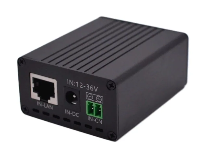
The Maxsol POE24V adjustable DC-to-PoE converter documents a 12–36V DC input, adjustable 12–57V PoE output, Gigabit Ethernet and an LCD voltage display. Its documented continuous load when converting 12V to 48V is at most 30W. The stated conversion efficiency of up to 94% is a maximum rather than a guaranteed design value.
IEEE powered-device detection or negotiation is not established by those product facts. Before connecting equipment, verify the selected output voltage, polarity, pinout, protocol, continuous load and behaviour at minimum battery voltage.
Calculate round-trip cable voltage drop
DC voltage-drop calculations must include the outgoing and return conductors. Using only the one-way distance understates both voltage loss and cable heating.
A practical calculation is:
[ R_{loop} = R_{conductor\ per\ metre} \times 2L ]
[ V_{drop} = I \times R_{loop} ]
[ P_{cable} = I^2 \times R_{loop} ]
where:
- (L) is the one-way cable distance;
- (R_{loop}) is total round-trip resistance;
- (I) is branch current;
- (V_{drop}) is cable voltage drop;
- (P_{cable}) is power dissipated in the cable.
Use the actual conductor resistance from the cable manufacturer where possible. Include relevant connectors, terminals, fuses and disconnects in measurements because their resistance is not represented by cable length alone. Conductor resistance also rises with temperature.
Hypothetical comparison at 12V, 24V and 48V
Assume the following solely to illustrate the method:
- load power: 120W;
- one-way distance: 60m;
- assumed conductor resistance: 0.0046Ω per metre;
- round-trip length: 120m;
- calculated loop resistance: 0.552Ω;
- conversion losses, startup current and temperature correction excluded.
| Bus voltage | Current for 120W | Calculated voltage drop | Cable power loss |
|---|---|---|---|
| 12V | 10A | 5.52V | 55.2W |
| 24V | 5A | 2.76V | 13.8W |
| 48V | 2.5A | 1.38V | 3.45W |
These are hypothetical calculations, not measured product results. They demonstrate why 12V distribution becomes difficult over distance: doubling the voltage halves the current, and cable loss falls with the square of current.
The percentage drop also matters:
- 5.52V is 46% of a 12V bus;
- 2.76V is 11.5% of a 24V bus;
- 1.38V is about 2.9% of a 48V bus.
A real design should recalculate using minimum source voltage, maximum expected current, actual installed cable resistance and the load’s minimum allowable input. If voltage drop is excessive, possible responses include increasing conductor size, shortening the DC run, moving conversion closer to the source, dividing the load into branches or using a higher distribution voltage.
PoE port consumption must be calculated separately from DC cable loss. Use the practical method in this PoE power-budget guide for security cameras before adding switch consumption and conversion losses to the source requirement.
Size branch protection and service isolation
A single main fuse does not adequately protect every smaller downstream conductor. Each branch should have protection selected around the weakest applicable current-carrying component, including the cable, connector, terminal and device input.
A practical distribution arrangement may include:
- main battery protection located close to the source;
- a DC-rated service disconnect;
- separate protection for the PoE switch or converter;
- separate branches for radios, lighting or auxiliary equipment;
- clear positive and negative identification;
- labelled spare circuits and documented fuse sizes.
Protection devices must be suitable for DC interruption at the maximum possible circuit voltage and fault current. An AC-rated device should not be assumed safe for DC merely because its current rating appears sufficient.
Fuse or breaker selection must consider:
- normal continuous current;
- startup and inrush current;
- cable current capacity under installed conditions;
- ambient enclosure temperature;
- bundled conductors;
- connector and terminal ratings;
- source fault capability;
- interrupt rating;
- applicable project and local electrical requirements.
Avoid oversizing a fuse simply to prevent nuisance operation. If startup causes repeated fuse or breaker operation, investigate the inrush profile, source sag and cable drop rather than removing protection.
Provide safe service isolation
Technicians should be able to isolate the battery, PV input where applicable, and load distribution without relying on unplugging live terminals. Disconnects need an appropriate DC voltage and current rating, accessible labelling and a layout that reduces accidental contact.
The isolation sequence should also account for controller requirements. Some solar controllers may require a particular battery-and-PV connection order, so follow the current controller instructions rather than assuming a universal procedure.
Manage enclosure temperature, moisture and bonding
Malaysia’s outdoor heat, humidity and rain exposure make enclosure design part of the electrical calculation. A sealed box can keep direct water out while still trapping internally generated heat and condensation.
Heat sources may include:
- DC converters;
- PoE switches;
- charge controllers;
- batteries;
- cable and terminal resistance;
- solar loading on the enclosure.
Equipment should be checked at the expected internal enclosure temperature, not only the outdoor air temperature. Leave appropriate clearance around heat-producing devices, avoid placing temperature-sensitive components directly above heat sources, and account for power derating specified by each manufacturer.
Moisture control requires more than selecting an enclosure label. Consider:
- cable glands sized for the actual cable diameter;
- drip loops before cable entry;
- downward-facing entries where practical;
- separation of wet and dry zones;
- drainage or pressure equalisation where suitable;
- corrosion-resistant terminals and hardware;
- inspection access for seals and condensation.
Do not block intentional vents or drainage paths to make a cabinet appear more sealed.
Plan bonding and surge paths deliberately
Metal enclosures, equipment earth terminals, cable screens and surge-protection devices require a coordinated bonding plan. Do not automatically connect DC negative to the enclosure or earth unless the system design and equipment instructions call for it. An unintended second bond can create circulating current, noise or unexpected fault paths.
Document:
- whether the DC system is floating or referenced;
- the designated bonding point, if any;
- enclosure and mounting-structure bonding;
- cable-screen termination;
- surge-protection connections;
- earth-conductor routing;
- separation between power and signal conductors.
Bonding and earthing arrangements should follow the current equipment instructions and applicable project requirements. Specific conductor sizes or earth values should not be selected from a generic article without considering the installation and local requirements.
Test worst-case voltage and recovery
Commissioning evidence should show what happens at the weakest point in the system, not only the voltage measured at the battery on a sunny day.
Record at least:
- battery-terminal voltage at rest;
- source voltage while all loads are operating;
- voltage before and after each main protection device;
- voltage at the remote converter or switch input;
- converter output voltage;
- branch current;
- total source current;
- startup minimum voltage;
- recovery time after startup;
- device restart or port-drop events;
- enclosure temperature during the test.
Use a meter with minimum/maximum capture or a suitable logger when brief sag cannot be seen reliably on a normal display.
Perform a controlled worst-case sequence
A practical commissioning sequence is:
- Verify polarity and open-circuit voltage before connecting loads.
- Start one branch at a time and record its current.
- Start all intended devices together.
- observe the lowest input voltage at the furthest or highest-load device.
- Confirm that converters remain within their input range.
- Test camera functions that increase demand, such as infrared illumination, heaters or motors where fitted.
- Apply representative radio traffic and network load.
- Disconnect and restore the source to verify orderly recovery.
- Check terminals and protection devices for abnormal heating.
- Save the final readings with the wiring diagram and settings.
For managed installations, monitoring can help distinguish a DC event from a network event. The Maxsol IOT2802SFG-S managed solar industrial PoE switch documents eight Gigabit PoE ports, two SFP ports, a 120W PoE budget, 90W BT support, and PV and battery monitoring. Its documented PV and battery input range is DC22–29.2V, with configurable 24V or 48V PoE on ports 3–4.
That input range means a nominal 12.8V battery kit is not a direct compatible input. Actual port allocation, charging limits, battery compatibility and supplied configuration must be confirmed from the current documentation. The linked switch, converter and solar system are selection examples, not a tested compatible bundle.
Choosing between 12V, 24V and 48V
Use 12V distribution when the loads are close to the source, current remains manageable and the equipment is genuinely compatible with the full 12V-class operating range. It can be convenient for small accessories, but voltage-drop margin disappears quickly as distance or power increases.
Choose 24V when compatible equipment is available and you need lower current than a 12V system without adopting a 48V bus throughout. Confirm whether “24V” equipment means a broad regulated input range or a narrow nominal requirement.
Choose 48V for longer distribution distances or larger centralised loads where reducing current and cable loss is important. Check maximum charging or supply voltage carefully: a device labelled 48V may not accept every 48V-class battery or power source.
Before approving any design, confirm:
- complete source voltage range;
- minimum load and converter input voltage;
- maximum continuous and startup current;
- PoE protocol, voltage, polarity and pinout;
- cable loop resistance;
- branch protection and disconnect ratings;
- thermal derating;
- battery charging restrictions;
- monitoring and recovery behaviour.
As a next step, compare the linked Maxsol models against your required port count, load, cable distance, DC voltage, environment and management needs. Treat each model as an individual selection option and verify the current datasheet and configuration before combining components.