Solar PoE vs Traditional Power for Remote Sites
Compare solar PoE and grid-fed outdoor PoE for remote sites in Malaysia across distance, civil work, uptime, maintenance and lifecycle cost.
By Maxsol Team

Solar PoE is usually the better option when extending utility power to a remote site would require substantial trenching, cabling, approvals or civil work. Traditional grid-fed PoE is often more practical where reliable AC power already exists nearby and continuous solar autonomy would demand a large PV and battery system.
Neither architecture is automatically better for every Malaysian site. A fair solar PoE vs traditional power comparison must use the same cameras, radios, network equipment, operating hours and recovery target. Distance, shade, weather exposure, maintenance access and future expansion can then determine whether solar, grid or a hybrid design offers the stronger lifecycle outcome.
Define the same remote-site load and service objective
Start by defining what the site must operate and how long it must remain available. Comparing a small solar installation against an AC system serving more devices or providing longer backup time will produce a misleading result.
Document the following for every powered device:
- Normal and maximum power consumption
- PoE standard or required output voltage
- Startup, heater, infrared or radio transmission peaks
- Required operating schedule
- Copper Ethernet or fibre uplink
- Environmental limits
- Criticality during an outage
- Planned future devices
For surveillance sites, do not calculate the load using only a camera’s typical daytime consumption. Night-time infrared illumination, integrated heaters, pan-tilt-zoom movement and wireless transmission can raise demand. Network switches, media converters, controllers and other enclosure equipment must also be included.
The service objective should answer four questions:
- Must the site operate continuously or only during selected hours?
- How much downtime is acceptable?
- How quickly can a technician reach the location?
- What happens if communications or power is lost?
A security camera at a critical perimeter may need continuous operation and remote fault reporting. A non-critical environmental sensor may tolerate scheduled operation or delayed recovery. These are different design objectives even when both sites are described as remote.
For solar, estimate daily energy rather than looking only at peak watts:
Daily energy demand = device power × operating hours
Calculate this for each load, then account for conversion losses, battery charging, cabling and design margin. Solar autonomy must also cover periods when PV generation is below expectation because of cloud, rain, dirt or shading.
For grid-fed equipment, confirm both the available AC supply and the required backup duration. A UPS power rating does not state how many hours the site will operate. Runtime depends on battery energy, total load, battery condition, conversion efficiency and operating temperature.
Compare energy source conversion and distribution
The main architectural difference is not PoE itself. It is how energy reaches the PoE equipment and how many conversion stages sit between the energy source and the endpoint.
Solar PoE architecture
A typical solar PoE path is:
PV modules → solar power control and charging → battery → DC-powered PoE equipment → cameras, access points or radios
Solar can avoid a long AC extension by generating and storing energy at the remote location. This is valuable for estate boundaries, isolated gates, temporary compounds, hilltop radio positions and other sites where utility power is distant or difficult to route.
However, the solar array and battery must be engineered as part of the network system. Undersizing either component can make a correctly configured PoE network unavailable simply because its energy reserve is insufficient.
The guide to solar-powered PoE for off-grid networking explains the relationship between the PV source, stored energy, PoE load and communications equipment in more detail.
As a product example, the Maxsol IOT2802SFG-S managed solar industrial PoE switch documents eight Gigabit PoE ports, two SFP ports, a 120W PoE budget, 90W BT support, and PV and battery monitoring. Its documented PV and battery input range is DC22–29.2V, while ports 3–4 can be configured for 24V or 48V PoE.
Those figures should not be treated as automatic system compatibility. Designers still need to verify actual port allocation, charging limits, battery compatibility, endpoint voltage requirements and the combined load under worst-case operation.
Grid-fed outdoor PoE architecture
A grid-fed outdoor system typically follows this path:
Utility AC → isolation and protection → power supply or UPS → PoE switch → cameras, access points or radios
If AC is already present near the device location, this architecture can be straightforward. The system is not constrained by daily solar generation, although it remains dependent on the quality and continuity of the incoming supply.
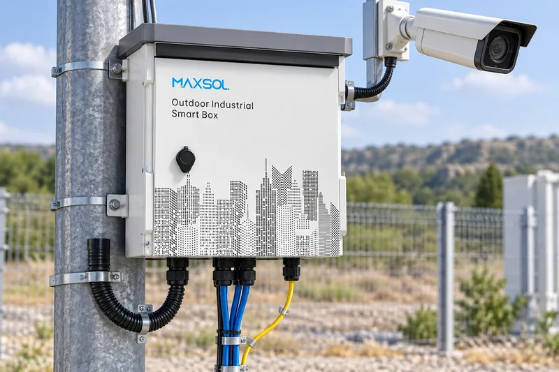
Outdoor grid-fed systems may combine power conversion, network switching, backup and environmental protection in one enclosure. The outdoor PoE switch box design guide covers the practical relationship between incoming power, fibre, battery backup and outdoor enclosure design.
For example, the Maxsol SBOX2802SFG-I managed industrial smart Ethernet box is documented as an IP65 unit with eight Gigabit PoE ports, two Gigabit SFP slots, Layer 2 management, AC100–240V input and a built-in 240W DC55V UPS module.
The 240W module rating is not a statement of backup duration. Actual runtime must be calculated from the verified battery arrangement, load and operating conditions.
These two Maxsol products illustrate different power architectures. They are not a tested equivalent pair, so they should not be compared as though all operating conditions, power capacity and backup requirements were identical.
| Decision factor | Solar PoE | Grid-fed outdoor PoE |
|---|---|---|
| Primary energy source | Local PV generation and battery storage | Available AC supply |
| Main design constraint | Solar yield, battery autonomy and load profile | AC extension, supply quality and backup requirement |
| Long-distance power work | Can avoid extending AC to the endpoint | May require trenching, cabling and distribution work |
| Operation during source loss | Depends on battery state and energy management | Depends on UPS or other backup provision |
| Monitoring priority | PV, battery, load and network status | AC input, UPS, battery and network status |
| Expansion limit | Available PV, battery and PoE capacity | Available AC, UPS and PoE capacity |
| Common design risk | Undersized array or battery | Assuming nearby AC is reliable or inexpensive to extend |
Evaluate installation distance and civil work
Distance is often the deciding factor for a remote site. The relevant measurement is not only the distance between the control room and camera. It includes the route that power and communications must follow around roads, drains, slopes, buildings, property boundaries and restricted areas.
When solar reduces installation scope
Solar PoE can place the power source beside the network endpoint. This may remove the need for:
- Long AC cable routes
- Utility distribution extensions
- Extensive trenching
- Road or drainage crossings
- Intermediate power cabinets
- Multiple AC conversion points
This does not mean solar requires no civil work. The site may still need a pole or frame, equipment enclosure, foundations, earthing, surge protection and a clear location for PV modules. Vegetation growth and new structures can also create future shading, so the solar survey must consider more than conditions on installation day.
When grid-fed PoE is simpler
Traditional power may be the lower-complexity choice when a verified AC circuit is already available at the exact equipment position. An outdoor enclosure can then supply and manage several local PoE devices without adding a separate solar array and battery system.
Do not assume that an AC source described as “nearby” is suitable. Confirm:
- The actual cable route rather than straight-line distance
- Available circuit capacity
- Voltage conditions at the endpoint
- Isolation and protection requirements
- Permission to use or modify the supply
- Exposure to water, lightning and physical damage
- Space for backup equipment
- Safe maintenance access
Separate data distance from power distance
Standard copper Ethernet channels are generally designed around a maximum 100-metre channel length. A remote camera beyond that distance may require fibre, a wireless bridge, an intermediate switch or another approved extension method.
Fibre can solve the data-distance problem and provide electrical separation between network segments, but it does not deliver power to the endpoint. The remote enclosure still needs solar, local AC or another verified energy source.
Where SFP ports are used, confirm transceiver type, fibre type, connector, link distance, speed and compatibility at both ends. The presence of an SFP slot alone does not guarantee that any transceiver or fibre design will work.
Compare monitoring, maintenance and recovery
Remote-site reliability depends on how quickly operators can identify a fault and restore service. A system that fails less often but provides no useful diagnostic information can still create expensive site visits.
Solar monitoring priorities
A solar PoE installation should make it possible to distinguish among:
- Low or missing PV input
- Battery voltage or state issues
- Excessive load
- PoE endpoint failure
- Network uplink failure
- Switch or controller fault
PV and battery monitoring, such as the documented functions on the IOT2802SFG-S, can provide useful visibility. It does not remove the need for correctly placed sensors, suitable thresholds or a response procedure.
Maintenance planning should cover:
- PV module cleanliness and shading
- Loose or corroded connections
- Battery condition
- Enclosure seals and cable entries
- Surge protection
- Earthing and bonding
- PoE port status
- Network and fibre connections
Malaysia’s heat, heavy rain, humidity and rapid vegetation growth can materially affect outdoor installations. Equipment selection, enclosure layout and inspection frequency should reflect the actual site exposure rather than relying only on a generic “outdoor” description.
Grid-fed system monitoring priorities
A grid-fed outdoor PoE site should differentiate between:
- Loss of incoming AC
- UPS or battery issue
- DC power-supply fault
- PoE overload or endpoint fault
- Switch failure
- Uplink failure
Remote switch management can help operators check port status, traffic and link conditions before dispatching a technician. However, network management cannot diagnose every physical problem, such as damaged AC cables, water entry or a disconnected battery.
Plan the recovery path
Ask what happens after the stored energy is exhausted or the incoming power fails.
For solar, recovery may depend on the next period of sufficient PV generation. If the battery has reached its protection threshold, confirm whether the system restarts automatically, in what sequence, and whether critical devices can be prioritised.
For grid-fed systems, recovery may occur when AC returns, but only if the UPS, power supply and PoE endpoints restart correctly. Confirm startup behaviour after a complete discharge and whether high inrush demand can prevent stable recovery.
For both architectures, prepare:
- Remote alarm thresholds
- A device restart sequence
- Critical and non-critical load priorities
- Replacement component compatibility records
- Safe local isolation procedures
- A method for temporary power during repair
Model lifecycle costs without invented prices
A valid lifecycle model includes more than the switch, solar panel or outdoor box. Use quotations and site measurements rather than applying a generic percentage or assumed payback period.
Calculate the lifecycle cost in consistent categories:
Lifecycle cost = initial equipment + design and installation + civil work + planned maintenance + expected replacement work + outage response + energy
Initial equipment
For solar, include the PV modules, mounting, battery system, charging and control equipment, PoE switch, enclosure, protection devices and communications uplink.
For grid-fed PoE, include the AC distribution work, outdoor PoE equipment, UPS or battery backup, enclosure, protection and communications uplink.
Installation and civil work
Include route surveys, trenching, poles, foundations, crossings, reinstatement, access equipment and any required site approvals. These costs are highly site-specific and can change the result more than the price of the PoE switch.
Maintenance and replacement
Solar designs may require PV cleaning, shading control and battery inspection or replacement. Grid-fed systems may require UPS battery maintenance, AC distribution inspection and repair of long cable routes.
Battery life cannot be inferred from chemistry alone. Temperature, depth of discharge, charge settings, cycle frequency and equipment compatibility all matter.
Outage and recovery impact
Estimate the operational consequence of failure:
- Technician travel and access time
- Equipment hire needed to reach the site
- Loss of surveillance or connectivity
- Repeat visits caused by incomplete diagnostics
- Temporary power or communications arrangements
Do not turn these factors into invented savings. Apply the organisation’s own labour rates, access costs, service targets and outage values.
Expansion cost
Future expansion can change the preferred architecture. Adding cameras to a grid-fed switch may be straightforward if AC, UPS and PoE capacity remain available. Adding the same load to solar may require a larger array, battery, controller or enclosure.
Check at least three design states:
- Current required load
- Expected expansion load
- Maximum credible load
For every state, verify PoE port count, per-port demand, total PoE budget, energy storage, uplink capacity and thermal conditions.
Select solar, grid or hybrid architecture by evidence
Use the site survey and load model rather than choosing by product category alone.
Select solar PoE when
Solar is a strong candidate when:
- No suitable AC supply exists at the endpoint
- Extending AC requires substantial civil work
- The site has a viable, low-shade PV position
- The load and operating schedule can be modelled accurately
- Sufficient battery autonomy can be designed
- PV and battery maintenance is practical
- Remote energy and network monitoring are available
Select grid-fed outdoor PoE when
Grid-fed PoE is generally suitable when:
- Verified AC is already available close to the equipment
- The incoming supply meets the load requirement
- The required outage backup can be provided
- Solar exposure is poor or heavily shaded
- Future load growth would make solar expansion difficult
- AC and UPS maintenance access is straightforward
Consider a hybrid or backup design when
A hybrid approach may be justified where the site is critical but either energy source alone has a significant limitation. Possible architectures include grid power with battery backup, solar with an alternative charging source, or separated critical and non-critical loads.
Hybrid does not automatically mean higher reliability. It introduces more components, operating modes and recovery logic. Confirm:
- Which source has priority
- How changeover occurs
- Whether batteries can be charged correctly from each source
- What happens during simultaneous source and communications failure
- Whether alarms identify the actual failed subsystem
- How the system restarts after full shutdown
Use a weighted decision matrix
Score each architecture against the same project priorities rather than adding unrelated advantages.
| Criterion | Questions to answer |
|---|---|
| Energy availability | Is AC present? Is solar exposure suitable throughout the year? |
| Required autonomy | How long must the full critical load operate without its primary source? |
| Civil work | What route, excavation, crossing and reinstatement work is required? |
| Load compatibility | Are voltage, PoE standard, port demand and total budget verified? |
| Communications | Will the uplink use copper, fibre or wireless? |
| Monitoring | Can operators distinguish power, battery, PoE and uplink faults? |
| Maintenance access | How quickly and safely can the site be reached? |
| Expansion | Can the architecture support likely additional loads? |
| Recovery | Will the site restart automatically and in the correct sequence? |
| Lifecycle cost | What are the verified equipment, installation, maintenance and outage costs? |
Common selection mistakes include comparing different backup durations, sizing solar from average load alone, treating a UPS power rating as runtime, overlooking night-time device demand, and assuming fibre also solves remote power delivery.
The practical next step is to complete a site load, distance and autonomy worksheet, then compare the linked Maxsol models against the required port count, endpoint load, cable or fibre distance, available power source, environmental exposure and management functions. Verify actual port allocation, power settings, battery compatibility and backup design before specifying either architecture.